-40%
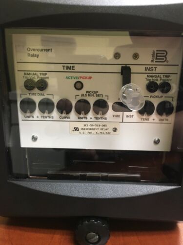
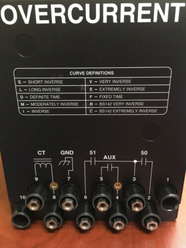
BASLER ELECTRIC BE1-50/51B-205 OVERCURRENT RELAY
$ 184.8
- Description
- Size Guide
Description
Like new without box still in bubble wraps.See details per instructional manual below for reference:
DESCRIPTION
BE1-51 Time Overcurrent Relays are microprocessor-based devices that monitor the magnitude of single- phase, two-phase-and-neutral, or three-phase-and-neutral ac current to provide accurate time overcurrent and instantaneous overcurrent protection for 50 hertz or 60 hertz power systems.
STANDARD FEATURES Time Overcurrent Functions
Time overcurrent elements pick up over a range of 0.1 to 0.8 amperes, 0.3 to 2.4 amperes, 0.5 to 4.0 amperes, 1.5 to 12.0 amperes, 0.1 to 2.4 amperes, or 0.5 to 12.0 amperes and provide an adjustable time delay that is proportional to the overcurrent. Time delay is initiated when the sensed current exceeds the pickup point. When the current drops below the pickup point, the timing circuit is reset immediately. At reset, the output contacts, if operated, are restored to normal.
Adjustment of the overcurrent pickup point is provided by controls on the relay front panel. Time delay is a function of the characteristic curve that has been selected. Time delay is settable from 00 to 99 on the TIME DIAL thumbwheel switch located on the front panel. Curve type is selected either as an option or, in some models, is switch selectable.
Sixty-nine characteristic curves and three timing options are available. They are: Characteristic curves:
• Seven inverse time
• Nine I2t
• Seven inverse time with extended timing range
• Nine I2t with extended timing range
• Five British Standard 142 (E curves)
• Seven integrating inverse time
• Nine integrating I2t
• Seven integrating inverse time with extended timing range
• Nine integrating I2t with extended timing range
Timing option Z1 (switch selectable - 16 position) B and C curves:
• Seven inverse time
• Nine I2t
Timing option Z1 with option 2-D or 2-E (switch selectable - 16 position) B and C curves:
• Seven inverse time with extended timing range
• Nine I2t with extended timing range
Timing option Z2 (switch selectable - 16 position) B and E (British Standard 142) curves:
• Seven inverse time
• One I2t
• Five British Standard (BS) 142 (E curves)
Timing option Z2 with option 2-D or 2-E (switch selectable - 16 position) B and E (BS142) curves:
• Seven inverse time with extended timing range
• One I2t with extended timing range
• Five British Standard 142 (E curves)
Timing option Z3 (switch selectable - 16 position) integrating B and C curves:
• Seven integrating inverse time
• Nine integrating I2t
Timing option Z3 with option 2-D or 2-E (switch selectable - 16 position) integrating extended B and C
curves:
Seven integrating inverse time with extended timing range
Nine integrating I2t with extended timing range
Characteristic curves are shown by the graphs in Appendix A, Time Overcurrent Characteristic Curves. Note that each graph (i.e. function) consists of a set of representative curves. Each curve (as well as any between-curve interpolation) is selectable by the front panel TIME DIAL using a two-digit destination from 00 to 99. Because of space limitations, each graph shows only 14 of the 100 possible selections.
Non-Integrating Timing
Timing options Z1 and Z2 and the characteristic curves available with those options use non-integrating timing. Non-integrating timing is accomplished by timing at a gate that is not solely dependent on the magnitude of the applied multiple of pickup current. The time-out value is calculated based on the type of time curve characteristic selected, time dial setting, and the magnitude of the applied multiple of pickup current. The time-out value is continuously updated during the timing cycle. When pickup is exceeded, a timer is initiated. When the timer elapsed time exceeds the calculated time-out value, a time trip output signal is generated.
This type of non-integrating time delay characteristic exhibits a dynamic characteristic that is immediately responsive to changes of the applied multiple of pickup current.
Integrating Timing
Timing option Z3 and the characteristic curves available for that option uses integrating timing. Integrating timing is accomplished by summing time increments that are based on the magnitude of the applied multiple of pickup current, the time curve characteristic selected, and the time dial value. These time increments are summed until a predetermined value is exceeded, then a time trip output signal is generated.
This type of integrating time delay characteristic simulates the operating characteristics of an electromechanical overcurrent relay.
Built-In Test
A built-in test (BIT) switch mounted on the Logic Board provides diagnostic troubleshooting and calibration.
MODEL AND STYLE NUMBER DESCRIPTION
Electrical characteristics and operational features included in a particular style of the BE1-51 Time Overcurrent Relay are defined by a combination of letters and numbers that make up its style number. The model number, together with the style number, describes the options included in a specific device, and appears on the front panel, drawout cradle, and inside the case assembly. Upon receipt of a relay, be sure to check the style number against the requisition and the packing list to ensure that they agree.
Style Number Identification Chart (Figure 1-1) illustrates the manner in which the relay style number is determined. For example, if the style number were H3E-Z1P-B2C1F, the device would have the following characteristics:
BE1-51 General Information:
Three-Phase-and-Neutral sensing
Sensing input range of 1.5 to 12.0 amperes for phase and 0.5 to 4.0 amperes for neutral Normally open outputs
Switch selectable time curves
Operating power derived from 125 Vdc or 120 Vac
Current operated targets
Two instantaneous elements
Push-to-energize outputs
Normally open auxiliary timed output relay
Semi-flush mounting
